The two repeaters we keep running on the Peloritani mountains: what's inside them and how to connect, even from far away via EchoLink and the SvxLink reflector.
IR9K-R
Analogue FM, RV60
145.750MHz
Our VHF repeater, on top of Monte Dinnammare. You'll also find it on EchoLink and on the SvxLink reflector, talkgroup 446.
Our DMR digital repeater, connected to the BrandMeister network. The status you see here comes straight from BrandMeister.
Output
430.100 MHz
Input
431.700 MHz (+1.6 MHz)
Color Code
1
BrandMeister ID
222389
Site
Monte Antennamare (Dinnammare)
Status
checking
IR9K-R: how it is built and how to make your own
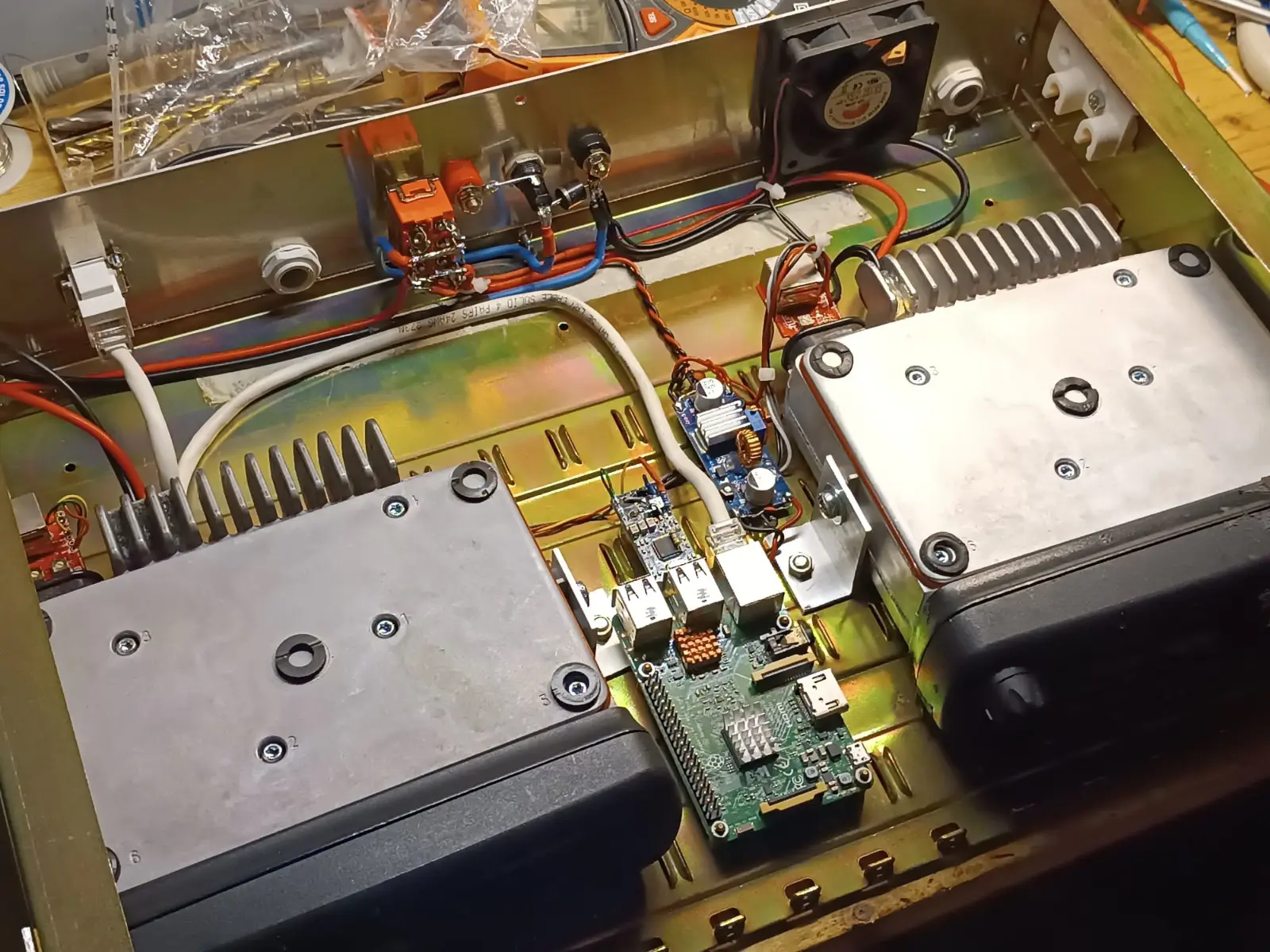
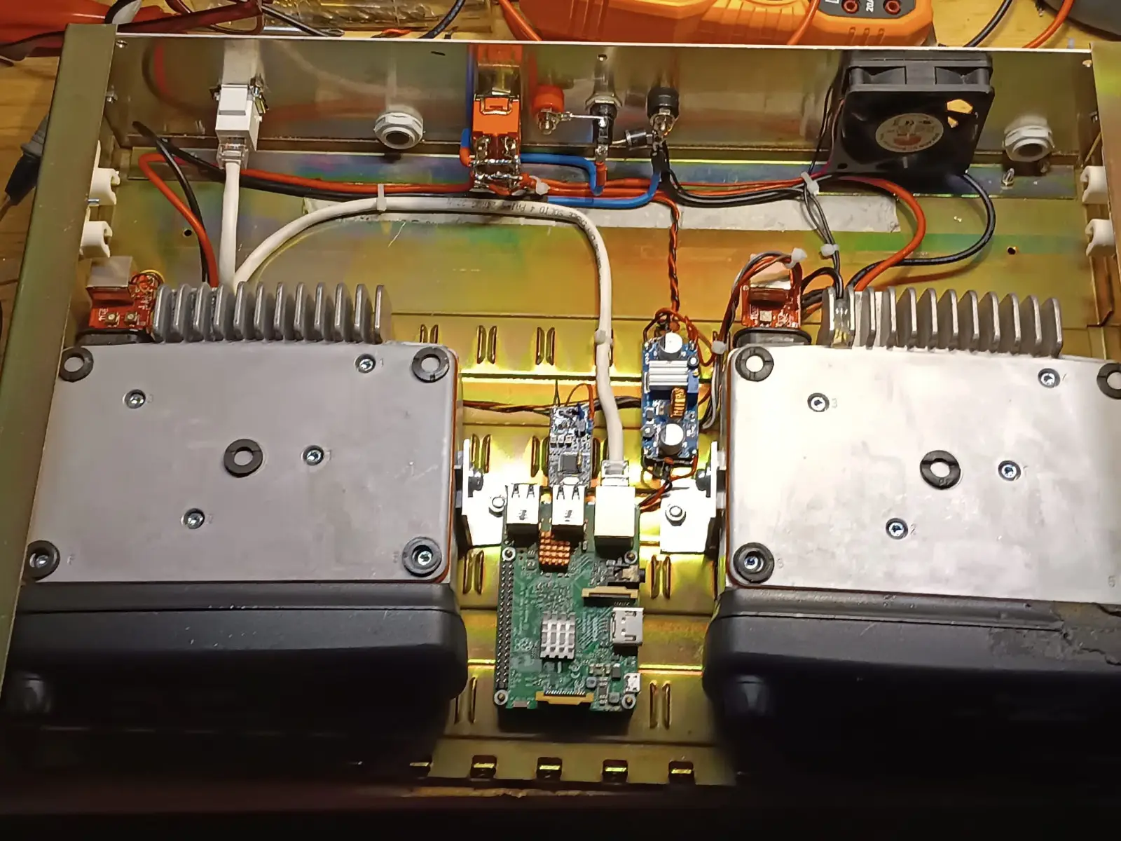
IR9K-R was built by Biagio IT9FDP, our Repeater Manager, out of simple gear that doesn't let you down: two Motorola GM340 transceivers and a Raspberry Pi running SvxLink, the free software for repeaters and nodes. Nothing exotic, which is exactly why it works.
One GM340 receives on the repeater input, 145.150 MHz: its audio goes into the Raspberry Pi's USB sound card.
The other GM340 transmits on the output, 145.750 MHz: it gets the audio from the sound card and keys up when SvxLink tells it to.
SvxLink riconosce i toni CTCSS e sceglie il talkgroup: 127,3 Hz → TG 446, 218,1 Hz → TG 1000 (il link sperimentale del reflector di Acireale). Ritrasmette chi parla, gestisce identificazione, roger beep e annunci in italiano. Il ponte resta sul 446 finché c'è un QSO e, se va sul 1000, dopo dieci minuti di silenzio torna da solo sul 446.
The repeater is linked to EchoLink as IR9K-R: any licensed amateur with a callsign validated on echolink.org can talk through it from a computer or smartphone, anywhere in the world. It is also linked to the SvxLink reflector on talkgroup 446.
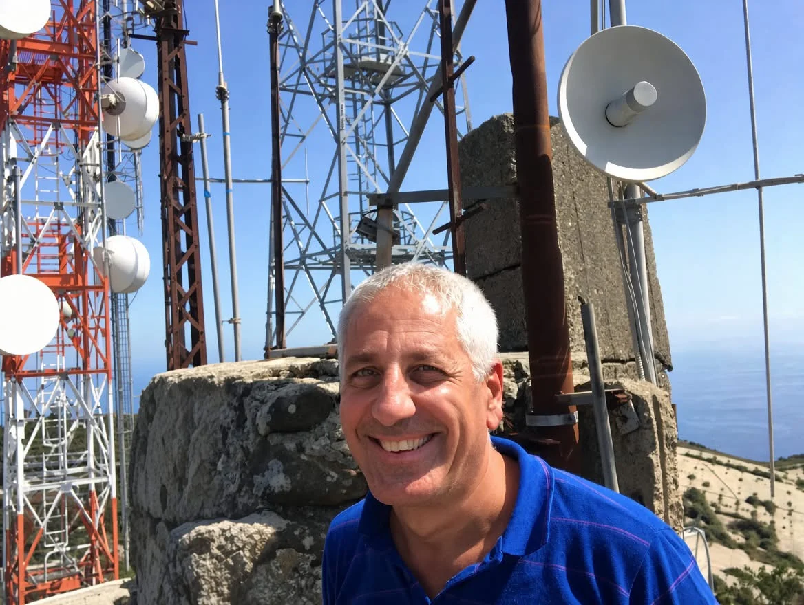
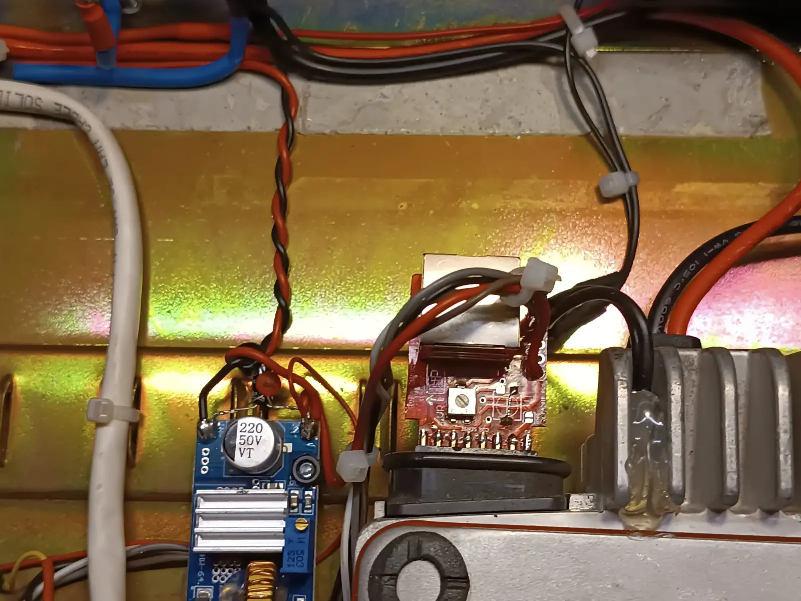
Biagio IT9FDP, the Section's Repeater Manager, among the antennasInside IR9K-R: the two GM340s on either side, the Raspberry Pi and the voltage converters in the middle; on the rear panel the sockets, the protections and the fanIR9K-R from above: the receiving and the transmitting GM340, with the Raspberry Pi between themDetail: a voltage converter and the interface board mounted on the back of a GM340
Come funziona IR9K-R: la voce ricevuta su 145.150 MHz passa dal Raspberry Pi e viene ritrasmessa su 145.750 MHz, e arriva anche su EchoLink e sul reflector (TG 446, TG 1000).
Come si entra nel TG 1000? Serve una radio FM programmata sull'uscita del ponte (145.750 MHz) con il tono 218,1 Hz: il tono, in questo caso, è quello che dice al ponte dove buttare il tuo audio — con 127,3 parli sul 446, con 218,1 parli nel TG 1000, e chi ci entra da internet o da Acireale ti sente sul 446 senza toni. In alternativa c'è il DTMF: 91 1000 #.
If you want to see what the repeater is doing right now, there's the live monitor. And if EchoLink is new to you, start with the EchoLink presentation (PDF, in Italian).
Building an SvxLink repeater with two GM340s
Fancy building one yourself? The same layout works with two mobile radios and a Raspberry Pi. Broadly speaking, this is how:
The two radios. They are programmed with the Motorola software (CPS): one on a single receive-only channel on the input frequency, the other transmitting on the output frequency at the desired power. To avoid interfering with each other you need well-separated antennas or a duplexer.
The accessory connector. The GM340 has a 20-pin accessory connector on the back with receive audio, transmit audio input, PTT and some lines programmable via CPS (for example a squelch-open output). Check the pins and their programming in the radio's service manual.
Audio to the Raspberry Pi. The audio output of the receiving radio goes to the mic input of a USB sound card, through a divider or trimmer to set the level. Unfiltered (flat) audio is better, leaving de-emphasis to SvxLink.
Audio to the transmitter. The sound card output goes to the transmit audio input of the second radio, with a trimmer to set the deviation.
PTT. SvxLink keys the radio through a USB serial adapter (RTS line) or a Raspberry Pi GPIO pin, always via a transistor or an optocoupler: never connect the radio directly.
Squelch. SvxLink can open the repeater by detecting the CTCSS tone in the audio itself, as IR9K-R does, or by reading the squelch line of the receiving radio.
Configuration. In SvxLink you define the receiver (Rx) and the transmitter (Tx) on the same sound card, the squelch type, the PTT, the identification and the modules, such as EchoLink.
Before putting it on the air, take the time to set audio levels and deviation properly and to make sure the repeater can never get stuck transmitting on its own (that's what transmit time-outs are for). For the details, Biagio IT9FDP is the person to ask: he's always happy to talk it through at the clubhouse.
IR9UM: the Section's DMR repeater
IR9UM is our DMR digital repeater, on channel RU4. It transmits on 430.100 MHz and listens on 431.700 MHz (+1.6 MHz offset) with colour code 1, from Monte Antennamare, with 5 W and an antenna at 10 metres. It's connected to the worldwide BrandMeister network with ID 222389; the trustee is Tullio IT9VJO.
This one was built by Biagio IT9FDP too, following the same recipe as IR9K-R: two Motorola GM340s, one receiving and one transmitting, this time connected to an MMDVM STM32-DVM modem board from Repeater Builder and from there to a Raspberry Pi running Pi-Star, which speaks DMR thanks to the free software MMDVMHost.
Two conversations at once: DMR splits the frequency into two time slots, so two different QSOs can go through the same repeater at the same time.
Talkgroups: talkgroup 222193 is always linked on Time Slot 1. Other BrandMeister talkgroups are activated by calling them from the radio, for example 222 Italy or 22291 Sicily.
Networked: through BrandMeister you talk with repeaters and hotspots all over the world. IR9UM's status is in the card at the top; who's talking right now is on BrandMeister Hose.
How IR9UM works: the receiving GM340 passes the DMR signal to the MMDVM board, the Raspberry Pi with Pi-Star routes it over BrandMeister and the transmitting GM340 retransmits it on 430.100 MHz.
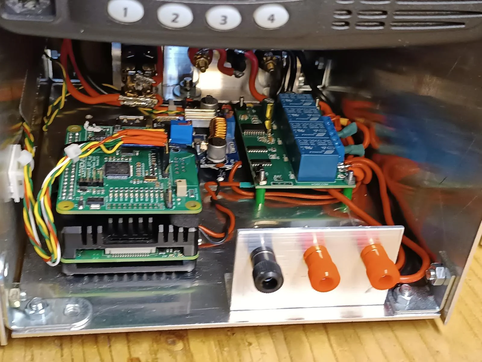
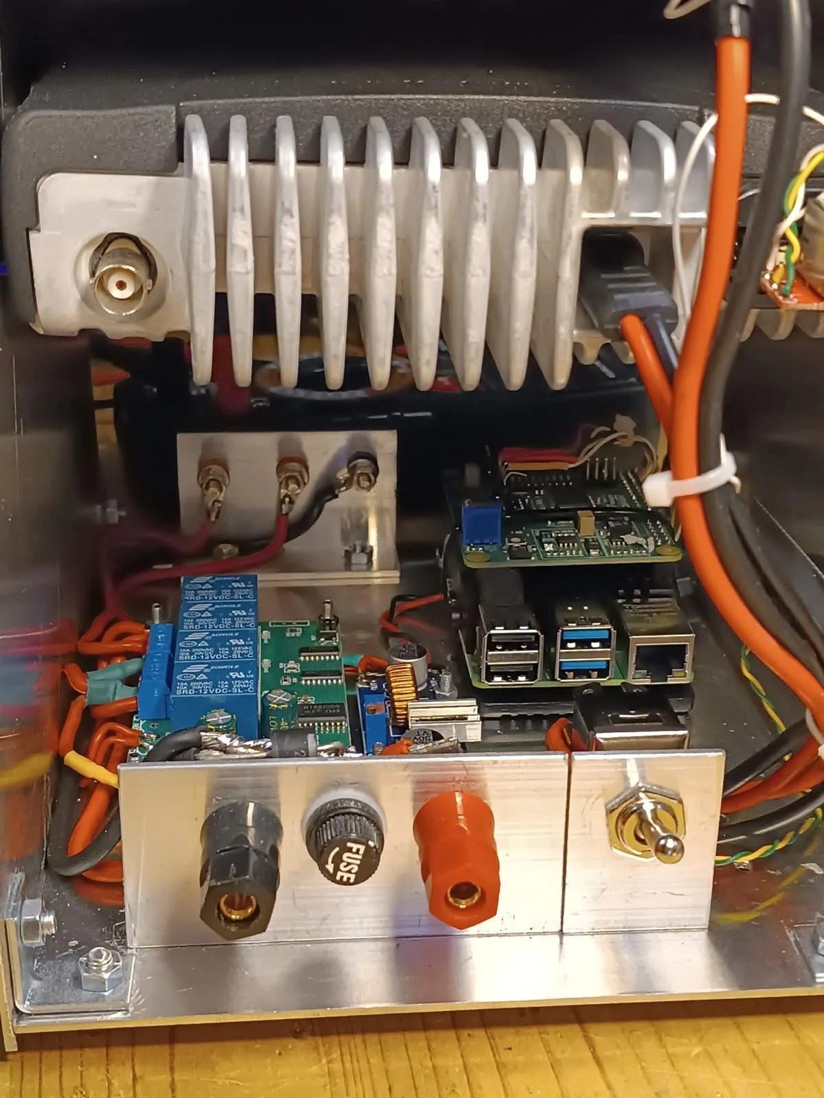
Inside IR9UM: under the GM340, the Raspberry Pi with the MMDVM board, the relay board and the power supplyIR9UM from the other side: the GM340 heatsink, the Raspberry Pi and the power terminals with fuse and switch
Programming your radio for IR9UM
To use IR9UM you need a DMR radio (Tier II) and a personal DMR ID, which you can request for free on RadioID.net with your callsign.
ID and callsign. Enter your DMR ID and callsign in the radio.
Contacts. Create group contacts for the talkgroups you are interested in: 222193, 222 (Italy), 22291 (Sicily), 9 (local).
Channel. Create a digital channel with receive 430.100 MHz, transmit 431.700 MHz, color code 1, and the time slot and talkgroup you want (for example TS1 with TG 222193).
RX group list. Add the talkgroups you want to listen to to the channel's receive list, so you hear them without changing channel.
Try it. Give the PTT a quick press: if the repeater answers, you're in. The callsign of whoever is talking will show up on the display.
If you want to understand more, there's the DMR presentation (PDF, in Italian). And if the codeplug scares you, bring your radio to the clubhouse: we'll write it together.
The installation: power, data link and protection
Below is the block diagram of how the installations up on the mountain are put together. The 230 V mains goes through surge arresters first and then to a 12 V power supply with a float-charged battery, which keeps the equipment running even when the power goes off (A). The 12 V feeds the 5 GHz data link (B) and the two repeaters, IR9UM (C) and IR9K-R (D).
Each unit has its own DTMF-controlled relay: so if something locks up, we can switch it off and on again from home without driving up the mountain. Everything coming in from outside, antennas and network cable included, goes through an earthed surge arrester. In each repeater a cavity duplexer lets it transmit and receive on a single antenna; on IR9UM an extra band-pass filter protects the receiver from the strong signals of the neighbours on the site.